Ultrafiltration in Industrial Wastewater Reuse: Design Basis, Pre-Treatment and Flux Sizing
Executive Summary
Ultrafiltration (UF) sits between biological treatment and final polishing in most industrial water reuse trains. It removes suspended solids, colloids, bacteria and most turbidity through a physical barrier, and it protects the reverse osmosis (RO) membranes that follow it. A UF system that is sized on an optimistic flux, fed with poorly screened water or cleaned without a plan will lose permeability within months, and the unit meant to protect the reuse plant becomes its bottleneck. This whitepaper sets out the design basis for UF in industrial wastewater service: how to define the feed, what pre-treatment the modules need, how to arrive at a defensible design flux, how the filtration, backwash and cleaning cycle should run, and where UF belongs in a train relative to MBR and RO. The examples lean toward textile and similar high-variability effluents, where UF is most often asked to do more than it can.
1. Why UF Has Become a Standard Stage in Reuse Trains
Discharge limits in India are tightening, and in several industrial clusters the pressure is not only about what leaves the plant but also about what the plant draws. Reuse closes that loop, and reuse at process-water quality almost always means RO. RO membranes tolerate very little in terms of suspended solids, colloids and biological matter in their feed, and a clarifier followed by a sand filter does not give a consistent silt density index (SDI) from one shift to the next. UF does. Its filtrate quality depends on the membrane pore size and not on how well the upstream sludge settled that day, which is why UF has moved from being an optional upgrade to a default stage ahead of RO in new reuse and ZLD designs.
2. How UF Works in Wastewater Service
UF membranes have pore sizes in the range of roughly 0.01 to 0.1 micron. That is small enough to retain suspended solids, colloidal matter, bacteria and many viruses, and large enough to pass dissolved salts, small organic molecules and most dissolved colour. In practice, the filtrate is very low in turbidity, with an SDI that is typically well within what RO manufacturers ask for. What UF does not do is reduce TDS, hardness or dissolved COD in any meaningful way, and a design that expects it to is already in trouble.
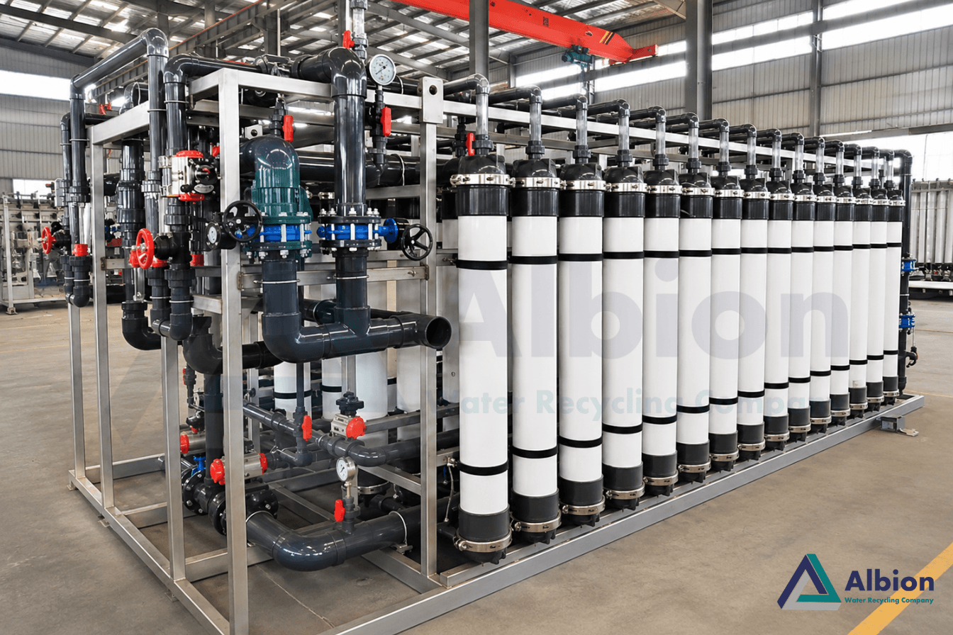
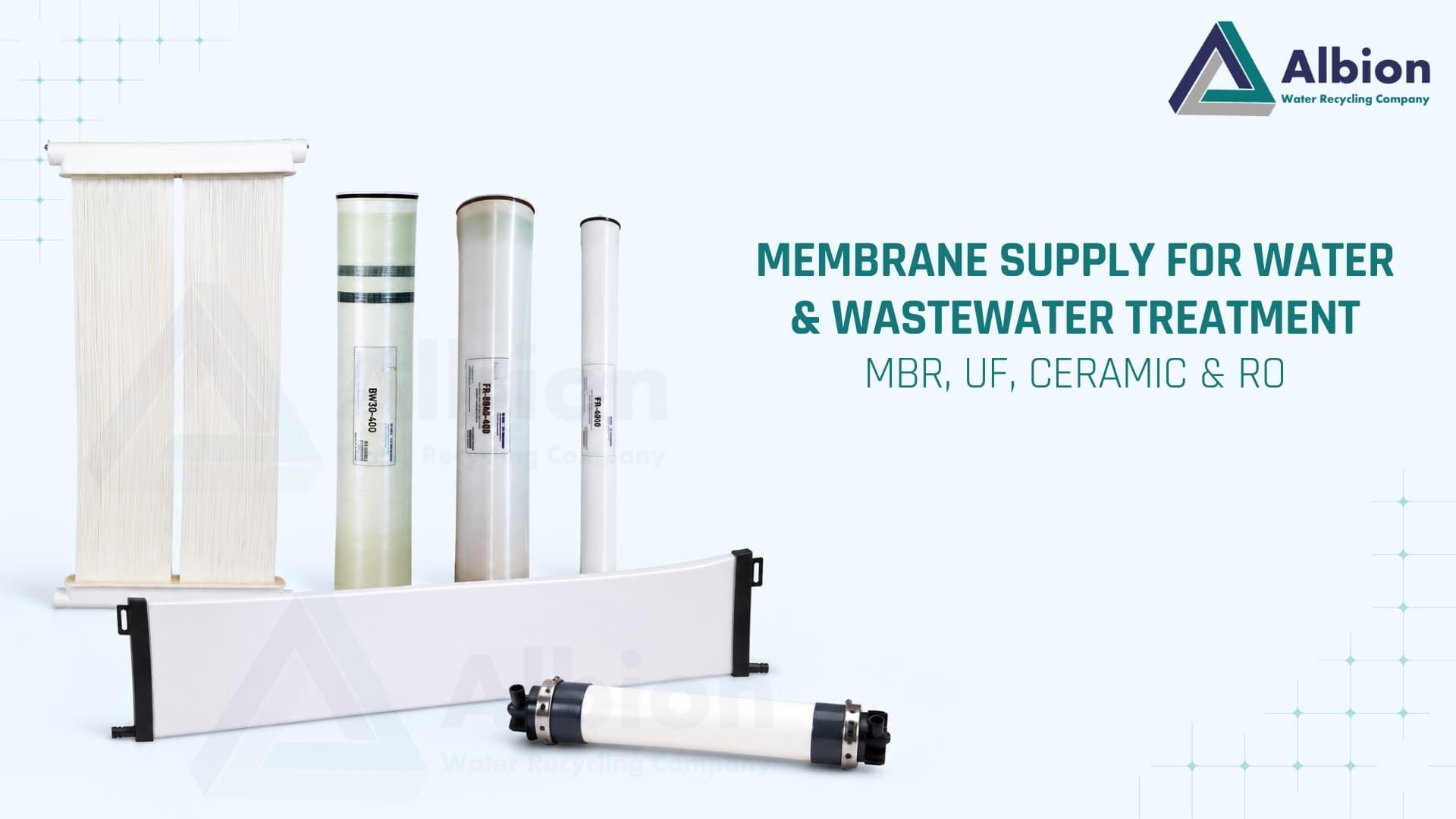
Industrial UF systems mostly use hollow-fibre modules made of polyethersulfone (PES) or PVDF, operated in dead-end or semi-dead-end mode with periodic backwash. Pressurised modules in vertical or horizontal skids are common in reuse trains; submerged modules are used where UF is built into a tank, as in an MBR. The choice of membrane material matters for chemical compatibility. PES and PVDF handle oxidants such as sodium hypochlorite differently, and the cleaning regime you plan to run has to sit inside what the membrane material and the manufacturer allow.
3. Defining the Feed Basis
Most UF problems trace back to a feed definition that was taken from a single lab report. The design basis should capture the range, not the average, and it should state what upstream stage the water comes from, because secondary clarifier overflow, tertiary filter outlet and MBR permeate behave very differently at the membrane surface. The parameters worth pinning down before sizing are listed below.
- Turbidity and suspended solids: the normal range and the upset range, since a clarifier carry-over event is what loads the membrane fastest.
- COD, BOD and TOC: particulate and colloidal organics foul UF; dissolved organics mostly pass through, but they feed biofilm growth on the membrane surface and in the permeate side piping.
- Oil and grease, surfactants, polymers: these coat the fibre surface and can cut permeability sharply even at low concentrations. Textile and food effluents often carry them.
- Hardness, iron, manganese and silica: they decide whether inorganic scaling is a realistic fouling mode and which cleaning chemicals will be needed.
- Temperature and pH: water viscosity changes with temperature, so permeability falls in winter and rises in summer. Hot process effluent has the opposite problem of limiting the membrane's allowable range.
- Residual oxidants and coagulants: free chlorine, overdosed ferric or alum, and cationic polymers all need to be known, because each can damage or irreversibly foul the membrane.
In textile effluent, two features need particular attention. Fibre and lint carried over from the process can wrap around hollow fibres and pack the module ends, so screening ahead of UF cannot be skipped. And dissolved dye passes through UF: if colour removal is part of the reuse target, it has to come from oxidation, adsorption or biological treatment upstream, or from nanofiltration or RO downstream.
4. Pre-Treatment Ahead of the Modules
A self-cleaning strainer is the minimum. Hollow-fibre module manufacturers specify a strainer rating, commonly in the range of 100 to 300 microns, and the strainer sits immediately upstream of the UF feed pump or feed header so that nothing downstream of it can add solids. A strainer on its own is not enough where the feed comes straight from a clarifier with variable carry-over. A dual media filter or activated filtration media (AFM) stage ahead of the UF takes the load off the strainer and flattens the solids peaks the modules would otherwise see.
Coagulant dosing ahead of UF can improve the removal of colloids and some organics, but it is not a default. Under-dosed or poorly mixed coagulant produces fine floc that passes the strainer and lodges in the fibre lumen. Over-dosed coagulant leaves a residual that adds to fouling. If inline coagulation is used, it should be validated at pilot scale on the actual effluent, with the mixing time and floc size matched to what the module can handle.
5. Sizing: Design Flux, Membrane Area and Skid Count
The core relationship is simple. Required membrane area equals the net filtrate flow divided by the design flux, expressed in litres per square metre per hour (LMH). The difficulty is in choosing the flux and in defining what net flow means. Net filtrate flow is the plant's required output plus the water used for backwash and cleaning, which comes out of the UF's own production. A system that needs a stated volume per day of usable water must be sized for more than that volume at the membrane.
Design flux for reuse-grade UF on treated industrial effluent usually sits in the tens of LMH, and the right figure depends on feed quality, module type, temperature and the cleaning regime the operators can sustain. Cleaner feed supports a higher flux; feed with colloidal organics, oils or polymer residue calls for a lower one. The manufacturer's guidance for the specific feed should set the ceiling, and a pilot run on the real effluent is the best way to confirm it before a large skid is built. Designing at the upper end of the manufacturer's range to save on membrane count tends to be paid back in cleaning chemicals, downtime and early module replacement.
Temperature needs an explicit correction. Permeability changes by roughly 2 to 3 percent per degree Celsius, so a plant sized on summer feed temperature will under-deliver in winter if no allowance was made. The sizing basis should state the design temperature, and trend data should be normalised to a reference temperature such as 20 °C so that real fouling is not mistaken for a cold morning.
Skid count is a reliability decision as much as a hydraulic one. With several skids, one can be taken offline for a CIP while the others carry the flow at a slightly higher but still acceptable flux. With a single skid, every cleaning is a full plant stoppage unless a storage tank downstream can ride through it. For plants feeding RO or a ZLD train, where interrupting the feed has consequences further along, N+1 skid arrangements are usually worth the additional piping and instrumentation.
6. The Operating Cycle: Filtration, Backwash, CEB and CIP
UF runs as a repeating cycle. Water is filtered for a set period, then the membrane is backwashed with permeate to lift the cake of retained solids off the fibre surface. In many installations the filtration step lasts in the order of 30 to 60 minutes and the backwash lasts for one to two minutes, though the right intervals depend on the feed and should be tuned during commissioning rather than copied from another site.
Backwash alone does not remove everything. A chemically enhanced backwash (CEB) adds a cleaning chemical to the reverse flow and is run at a lower frequency, often once a day or every few days. Sodium hypochlorite is typical for organic and biological fouling, and an acid such as citric acid for inorganic scale and metal hydroxides, provided the membrane material allows both. When permeability still drifts downward despite backwashes and CEBs, a clean-in-place (CIP) is run: the module is isolated, filled with a heated cleaning solution, soaked and flushed. A CIP should be a planned event rather than an emergency response, and the system should include a dedicated CIP tank, pump, heater and neutralisation arrangement from the start.
The signals that tell the operator when to intervene are transmembrane pressure (TMP) and temperature-normalised permeability. A TMP that climbs slowly across a filtration cycle and resets after backwash is normal. A rising baseline TMP, cycle after cycle, means the backwash is no longer recovering what the filtration step is losing. Tracking both values against time, and setting alert thresholds below the manufacturer's maximum TMP, gives the operator room to act before a CIP becomes a recovery exercise.
7. Fouling Modes and What Each Needs
- Particulate and colloidal fouling: largely reversible by backwash. Persistent particulate fouling points to a pre-treatment shortfall, not a cleaning problem.
- Organic fouling: oils, surfactants, polymers and humic-type compounds adsorb to the membrane. Oxidant-based CEBs and alkaline CIPs address it, within the membrane's chemical limits.
- Biofouling: bacteria colonise the fibre surface and the dead zones in piping. Regular oxidant dosing in CEBs, avoiding stagnant sections and keeping the filtrate tank turned over help to control it.
- Inorganic scaling and metal deposits: calcium carbonate, iron and manganese deposits dissolve in acid cleaning. They are more likely where UF follows a lime or coagulant stage, or where the water is hard and its pH has been raised.
8. Where UF Fits in the Treatment Train
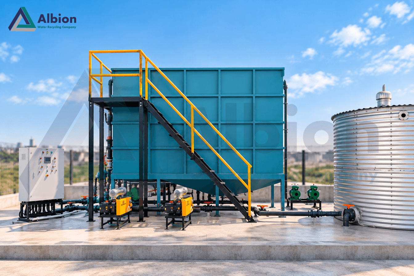
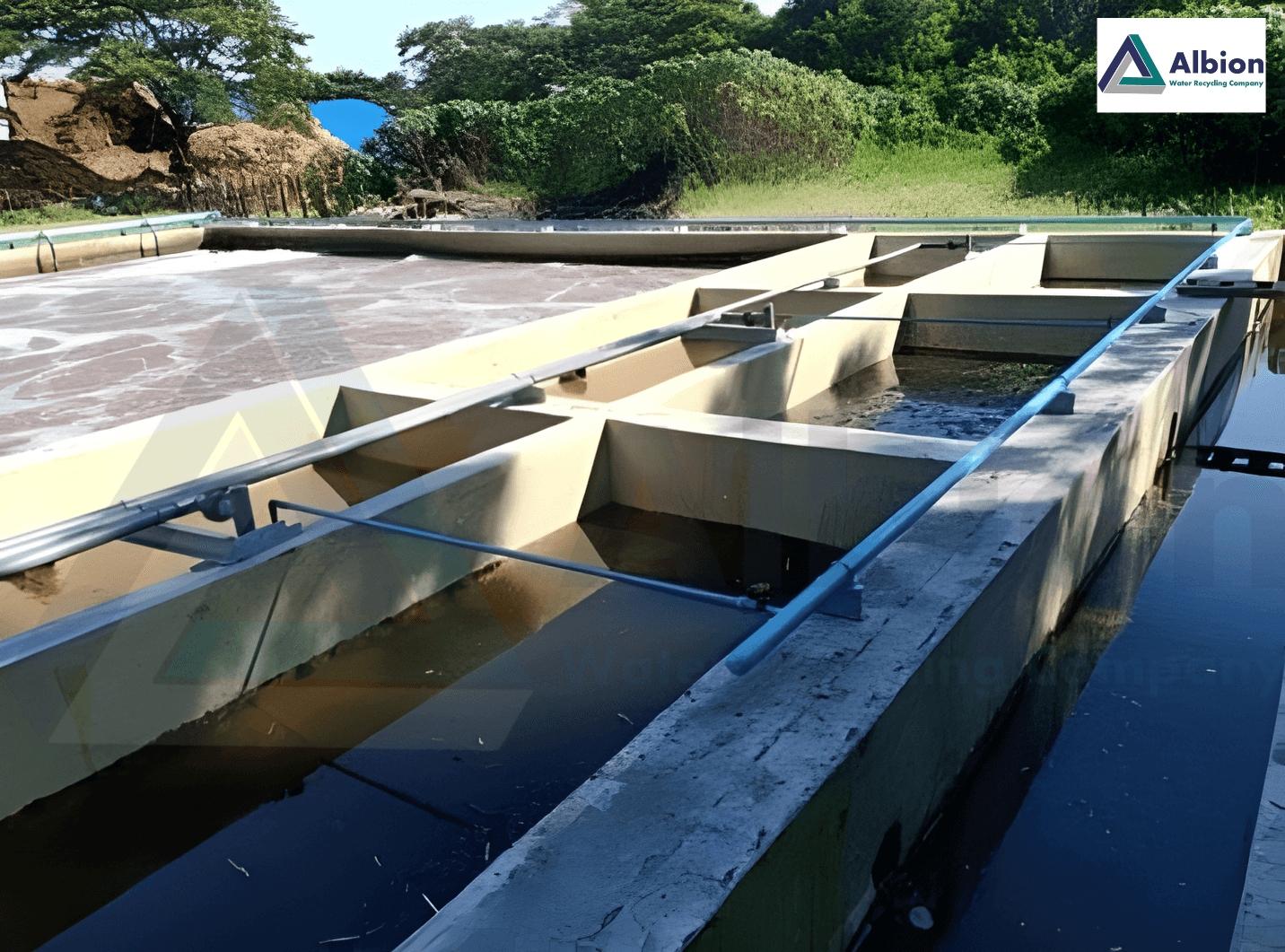
A typical reuse train for industrial effluent runs equalisation, biological treatment, secondary clarification, filtration, UF, RO and then, for ZLD, evaporation or crystallisation of the RO reject. Each stage hands a cleaner stream to the next, and UF's job in that chain is to give RO a feed whose quality does not depend on the clarifier's performance on a given day. Placing UF directly on poorly treated secondary effluent, without a filtration step in between, shortens the cleaning interval and raises the chemical bill.
The relationship with MBR deserves a clear statement. An MBR already uses a UF- or MF-class membrane inside the biological stage, so its permeate is membrane-filtered. Adding a separate UF stage after an MBR adds little for solids removal, and the permeate can usually go straight to RO or to a cartridge filter ahead of it. UF earns its place after conventional activated sludge, after an AMBBR with downstream clarification, or after any biological process whose final solids separation depends on gravity settling.
9. Design Mistakes That Show Up Repeatedly
- Sizing on a single feed sample and not on the range, including upset conditions.
- Skipping the strainer or specifying one that is coarser than the module manufacturer allows.
- Forgetting that backwash and cleaning water consume UF production, so the usable output falls short of the design number.
- No allowance for winter temperature in the flux basis.
- A single skid with no downstream storage, so every CIP stops the plant.
- Letting chlorine, ferric or cationic polymer residuals reach the membrane without checking compatibility.
- Expecting UF to reduce colour, TDS or dissolved COD.
10. Albion Ecotech's Perspective
Albion Ecotech supplies the U-Flocs UF system alongside X-Flocs MBR, C-Flocs ceramic MBR and Activated Filtration Media, and designs UF as part of the whole reuse train and not as a standalone package. For each project the team starts from the feed range and the end-use specification, decides whether UF belongs at all given what is upstream, and then selects pre-treatment, design flux, skid arrangement and the cleaning system together. Where the effluent is high in fibre, oil or polymer residue, as in textile and food streams, the design leans toward conservative flux and a dedicated filtration stage ahead of the modules, and the commissioning plan includes tuning the backwash and CEB intervals against actual TMP data from the site.
Frequently Asked Questions
What is a typical design flux for ultrafiltration on treated industrial effluent?
There is no single figure. Design flux depends on feed quality, module type, temperature and the cleaning regime, and the module manufacturer's guidance for the specific feed should set the limit. A conservative design flux with enough skids to allow for backwash and cleaning downtime is more reliable than an aggressive one.
Does ultrafiltration remove colour from textile wastewater?
Not reliably. UF retains suspended particles, colloids and bacteria, but dissolved dyes pass through the membrane. Colour is handled upstream through biological treatment, oxidation or adsorption, or downstream through nanofiltration or reverse osmosis.
Why is pre-treatment needed ahead of UF?
Hollow-fibre UF modules can be blocked by fibres, lint, grit and carried-over floc. A fine strainer, and often a filtration stage such as a dual media filter or activated filtration media, protects the fibres and keeps the cleaning frequency manageable.
What is the difference between a backwash, a CEB and a CIP?
A backwash is a short, frequent reverse flow of permeate that dislodges surface solids. A chemically enhanced backwash (CEB) adds a cleaning chemical to that reverse flow at a lower frequency. A clean-in-place (CIP) is a longer, deeper soak with chemicals, done when permeability has dropped despite backwashes and CEBs.
Should UF be placed after an MBR?
Usually not. MBR permeate is already membrane-filtered, so UF adds little for solids removal. UF is more commonly placed after a conventional biological process and clarifier, or after an AMBBR with downstream clarification, particularly when the water is going on to reverse osmosis.