Dissolved Air Flotation in Industrial Effluent Treatment: Design Basis and Operating Control
Executive Summary
Dissolved air flotation (DAF) is one of the most widely used pre-treatment steps in industrial effluent plants. It separates oil, fat, fibre and light suspended solids by attaching them to fine air bubbles and skimming them off the surface, and it does the job in a smaller footprint than a gravity clarifier. A DAF that is well conditioned and well controlled protects everything after it, including biological reactors, MBR and AMBBR stages, and UF membranes. A DAF that is not will run, produce a float layer, and still pass most of the load downstream. This whitepaper covers what DAF can and cannot remove, where it belongs in an effluent train, the design basis for sizing, the chemical conditioning that decides most of its performance, and the operating checks that keep it in control.
1. Where DAF Is Used
DAF suits effluents carrying material that is light, finely dispersed or hard to settle. Dairy, edible oil, meat and food processing wastewater carry fat and oil. Textile and paper effluents carry fibre, lint and fine solids. Oily wastewater from engineering and automobile units carries emulsified oil, and effluents from several chemical and pharmaceutical processes carry colloidal solids that settle poorly. In common effluent treatment plants, where the feed mixes several industries, DAF acts as a buffer against the fats, oils and fibres that individual members send in.
It is a poor choice for effluent that is mostly dissolved. A high-COD stream whose organic load is truly dissolved will pass through a DAF with little change, whatever the chemical dose. The same holds for salts and dissolved colour. DAF removes the part of the pollution that exists as particles or droplets, and that is the part to quantify before deciding to install one.
2. How the Process Works
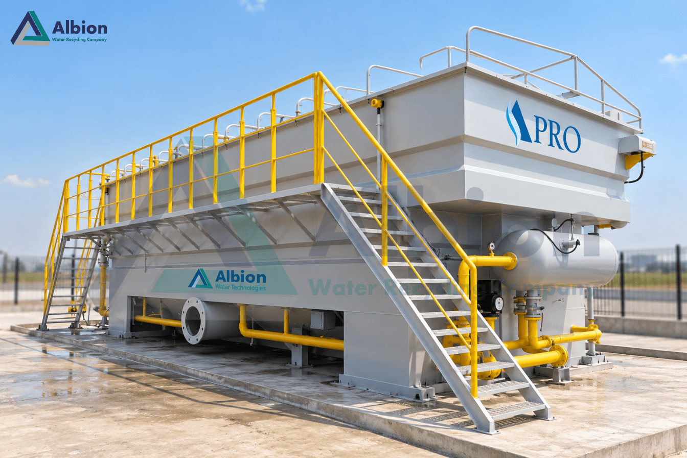
A portion of the treated water, the recycle, is pumped to a saturator where air is dissolved in it under pressure. The pressurised recycle is then released through a valve or nozzle into the flotation tank, where the pressure drops to atmospheric. The dissolved air comes out of solution as a cloud of very fine bubbles, in the range of tens of microns. The bubbles attach to conditioned flocs and oil droplets, lower their effective density, and carry them to the surface as a float. A skimmer moves the float layer into a hopper, and the clarified water leaves from below, usually through a baffle or an underflow weir.
Bubble attachment is what makes this work, and it depends on the particles being the right size and the right surface condition. That is why chemical conditioning is not an optional extra on a DAF. For emulsified oils and colloids it is the whole process.
3. Design Basis
As with any separation unit, DAF sizing starts from the feed definition. The design basis should record the flow range including peaks, the suspended solids, oil and grease and COD (total and soluble), pH, temperature, the type of oil or fat and whether it is free or emulsified, and any variability from batch discharges or cleaning cycles. Because the removal depends on how the particles respond to conditioning, a jar test or a bench flotation test on a representative sample is the most reliable way to set the chemical programme, and a pilot run is worth it for large or unusual effluents.
The main sizing parameters are these.
- Surface loading rate: the flow, including recycle where it enters the tank, divided by the flotation surface area. A lower rate gives the bubbles and flocs more time to rise and gives cleaner water. Light, well-conditioned floc tolerates a higher rate than oily or fibrous feed.
- Solids loading: the mass of solids per unit area per hour. A feed with a high solids concentration needs more area than the hydraulic rate alone would suggest.
- Recycle ratio and saturator pressure: together they set how much air reaches the flocs per unit of solids, usually expressed as an air-to-solids ratio. Recycle is commonly a modest fraction of the throughput, and saturator pressure is typically a few bar, though both should be set from testing on the actual effluent.
- Flocculation time: enough residence time and gentle enough mixing for the floc to grow, but not so much that it shears.
- Float handling: skimmer speed and frequency, float hopper size and the sludge pump or transfer arrangement. Float is wet, typically a few percent solids, so the downstream thickening and dewatering must be sized for it.
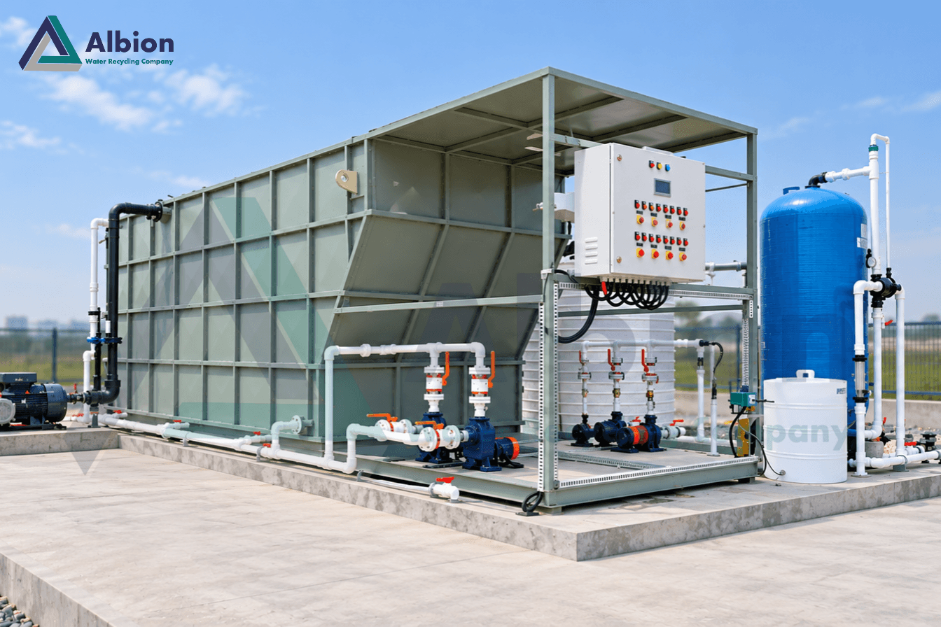
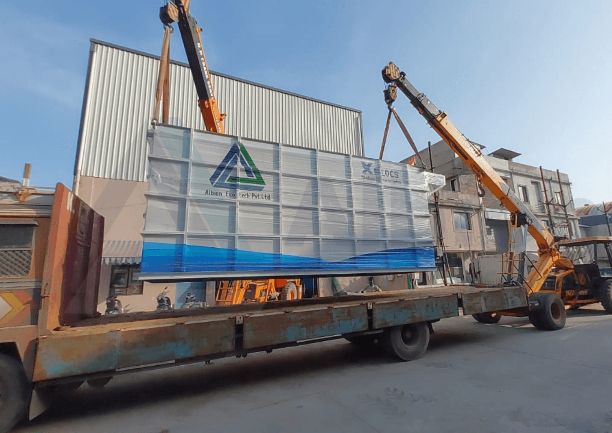
Material of construction needs attention in effluents that are acidic, saline or hot. Stainless steel and coated or FRP tanks are common choices, and the pump, nozzle and skimmer materials should be matched to the chemistry. In industrial plants with limited space, packaged skid-mounted DAF units with integrated saturator, flocculation chamber and skimmer reduce site work and commissioning time.
4. Chemical Conditioning
Fine particles and emulsified oil droplets carry a surface charge that keeps them dispersed. A coagulant such as aluminium sulphate, polyaluminium chloride (PAC) or ferric salt neutralises that charge and, under the right pH, forms hydroxide flocs that capture colloids and oil. A polymer, usually an anionic or low-charge-density polyelectrolyte, then bridges the small flocs into larger, stronger ones that bubbles can lift. Each step has its own working window.
- pH: coagulants work within a pH range that depends on the chemical, and the effluent often needs correction before dosing. A pH swing from a cleaning cycle can undo the dosing programme for an hour.
- Mixing: coagulant needs fast, intense mixing for a short time; polymer needs gentle mixing so that the floc forms without breaking.
- Dose: too little leaves colloids unflocculated; too much restabilises the particles and raises residual metal in the treated water and the cost of the sludge. Fixed doses on a variable feed are a frequent source of poor results.
- Interaction with later stages: carry-over of residual coagulant or cationic polymer can affect biological treatment and foul membranes, so the DAF dose has to be checked against what sits downstream.
5. Placement in the Treatment Train
The usual position is after screening and equalisation and ahead of the biological stage. Equalisation matters because DAF performance depends on a reasonably steady feed, and a tank that evens out flow, pH and load makes the conditioning programme easier to hold. Ahead of an MBR or AMBBR, a DAF takes out oil, fat and fibre that would otherwise coat biomass, foul membranes or clog carrier screens. It can also reduce the organic load reaching the biology, to the extent that load is bound to the removed solids.
A DAF can also be used after biological treatment, as a clarifier substitute where the biomass floats better than it settles, or as a tertiary step ahead of filtration. In textile plants, a DAF after biological treatment with coagulant dosing can remove a share of colour and residual solids ahead of UF or RO. In every case the sludge handling downstream has to be ready for the float.
6. Operating Control
Most DAF problems show up first at the surface. A thick, stable, evenly bubbled float with clear water below it indicates good conditioning. A thin float with cloudy water below means the flocs are too small, the dose is off or the air is insufficient. Large floc settling to the bottom means the particles are too dense for the bubbles available, or the recycle has dropped. A daily routine that includes a look at the tank, a jar test on a fresh sample when the feed changes, and checks of saturator pressure, recycle flow, nozzle condition, dosing pump output and skimmer operation catches most issues before the effluent quality moves.
Instrumentation that earns its cost includes an inline pH meter with control on the coagulation stage, flow metering on the feed and the recycle, a pressure gauge or transmitter on the saturator, and, where the feed varies, a turbidity or streaming-current type signal to trim the coagulant dose. Float removal should be timed to what the unit actually produces, since a float layer that sits too long breaks up and drops solids back into the water.
7. Troubleshooting
- Cloudy outlet, thin float: check pH, coagulant and polymer doses, mixing energy and the fresh-sample jar test.
- Floc settling instead of floating: check saturator pressure, air supply, recycle flow and blocked nozzles.
- Float breaking up or carrying over the weir: increase skimmer frequency, reduce surface loading, and check for excess polymer or shear.
- Good removal on some days and poor on others: look at the feed, not the DAF. Batch discharges, cleaning-in-place wastes and changes in production often shift pH, oil load and solids faster than a fixed dose can follow.
- Very wet float, heavy sludge volume: check skimmer timing and the thickening step ahead of dewatering.
8. Common Design Mistakes
- Installing DAF on an effluent whose pollution is mostly dissolved.
- Sizing on average flow without allowing for peak flow and for the recycle.
- Omitting equalisation, so the DAF sees every spike in flow, pH and oil load.
- Setting the chemical programme from a handbook and not from a jar test on the actual effluent.
- No provision for the float: undersized hopper, no thickener, no disposal route.
- Ignoring what the dosed chemicals do to the biological or membrane stage downstream.
9. Albion Ecotech's Perspective
Albion Ecotech supplies the A-Pro DAF system as a pre-treatment stage within complete ETP designs, ahead of X-Flocs MBR, M-Flocs AMBBR and U-Flocs UF where the effluent carries oil, fat, fibre or colloidal solids. The team treats the DAF as part of the whole train: the feed is characterised first, the chemical programme is set from jar tests, and the DAF is sized together with equalisation and with the sludge handling that follows it. Commissioning includes tuning the dosing and recycle against actual effluent quality, and operator training covers reading the float and running the jar test so that the unit stays in control when the feed changes.
Frequently Asked Questions
What does a DAF unit remove from industrial effluent?
It removes suspended solids, oil and grease, fats, fibres and colloidal matter that float when attached to fine air bubbles. With chemical conditioning it also removes a share of the COD that is bound to those solids. It does not remove truly dissolved COD, salts or dissolved colour.
Why is coagulation and flocculation needed before DAF?
Fine and colloidal particles carry a surface charge that keeps them apart and prevents bubbles from attaching. Coagulant neutralises that charge and polymer builds the particles into flocs that the bubbles can lift. Without conditioning, a DAF unit removes little more than free oil and coarse solids.
How is the DAF recycle ratio chosen?
The recycle flow carries the dissolved air, so the ratio sets how much air is available per unit of solids. It is selected from the air-to-solids requirement for the effluent, confirmed in a pilot or jar test with a flotation cell, and then trimmed during commissioning.
Should DAF be placed before or after biological treatment?
In most industrial effluent plants it goes ahead of the biological stage, to take out oil, fibre and solids that would disturb the biology or foul membranes. It can also be used after biological treatment as a clarifier substitute where the biomass floats better than it settles.
What causes poor float quality or carry-over in a DAF?
Common causes are wrong coagulant or polymer dose, pH outside the working range, low saturator pressure or an air supply problem, blocked nozzles, an overloaded surface area, or a skimmer that runs too seldom. A jar test with a fresh sample usually points to the cause.